The Series
This article is the fifth article in the Stairway Series: Stairway to Biml.
Biml is a markup language that enables you to quickly represent a variety of database related models and constructs, including SSIS packages, models, permissions and more. This stairway helps you get started using the language to represent your objects.
You are likely reading this series to learn how to be a more productive SQL Server Integration Services developer. I applaud your desire and decision, and I sincerely hope the information contained herein has provided ideas and information to help you be more productive. I am always on the lookout for ways to become a better data integration developer. Specifically, I seek out ways to improve code quality and reduce the amount of time required to build solutions. Those goals motivated me to begin practicing patterns-based development in the first place, which eventually led to the idea for the SQL Server 2012 Integration Services Design Patterns book.
Up to this point in the Stairway to Biml series, all of the Integration Services packages were created from one Biml file. Using multiple files enables the reuse of common code elements, which allows you to create a more modular approach to your Biml project. A modular design enables smaller, more interchangeable blocks of code that can make development, maintenance, and troubleshooting easier based on smaller units of work.
Article Foundation
There are some concepts that we need to understand before moving on with any Biml design patterns or best practices. It should be well acknowledged that you need a basic understanding of Integration Services prior to working with Biml. If you need more information on Integration Services, see the Stairway to Integration Services series. An understanding the basics of the Biml language is also required. The prior articles in the Stairway to Biml series should have introduced you to those items. If you skipped those articles, I would recommend reading the prior articles in the Stairway to Biml series before reading this article.
In this article, we will build upon our Biml knowledge by defining the elements that are available within the Biml Language. With the knowledge of these elements, we will be able to expand on design options that can enable a more robust Biml project. Once you have a thorough understanding of the language elements that are available and how to use them, you can move forward with development methodologies, best practices and efficient project design. This article will define and give examples of the elements that are available within the Biml Language.
The example code used in this project can be executed in Visual Studio 2008, 2010, and 2012 with the BIDS Helper Add-in Installed. If you do not have BIDS Helper installed, see the previous Stairway to Biml article: Biml Basics – Level 2.
Quick Primer on XML
Biml is a language based on XML. I will start with defining a few key terminology items in XML prior to discussing the Biml Language Structure.
XML Tag – A markup language construct that begins with < and ends with >. There are three types of Tags:
- Start Tags; for example: <Package>
- End Tags; for example: </Package>
- Empty-Element Tags; for example: <Package />
Note: An element with no content is said to be empty and is denoted using an Empty-Element Tag. This is represented by either a Start Tag and End Tag (<Package></Package>) or the abbreviated syntax <Package/>.
XML Element – the item within a Start or End Tag; in this example <Package>, “Package” is the Element within the Start Tag.
XML Attribute – A name/value pair that exists within a Start Tag or Empty-Element Tag. Attributes are generally used to describe the Element.
Let’s use an example to better define the above key terminology. In Figure 1 below, <Packages> and <Package> are XML Elements. Name and ConstraintMode (in red) are XML Attributes of the <Package> Element.
The <Packages> Element is defined with a beginning Start Tag and ends with an End Tag.
The <Package> Element is defined with an Empty Element Tag and contains two Attributes: Name and ConstraintMode.

Figure 1 – XML example items
Note: for more information on XML see: the Stairway to XML series at: http://www.sqlservercentral.com/stairway/92778/ or the ever so fun XML specification: http://www.w3.org/XML/
Biml Language Structure
To better understand the Biml Language we will describe the elements of the programming language and give examples of each. The below diagram breaks out the Biml Language into its component parts (Biml and Biml Script), their sub-parts and their applicable programming languages and syntax.
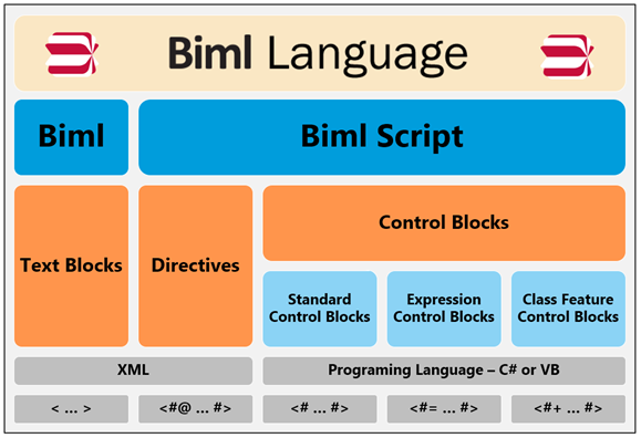
Figure 2 – Biml Language Structure
Note: In this article I will use the term “Biml” when referencing the Blue column entitled “Biml” which includes Text Blocks and is part of the XML language.
Biml and Biml Script
The Biml Language is first broken down into two main components: Biml and Biml Script.
Biml sections are the XML within a Biml file that define the elements of a Microsoft Business Intelligence solution. As a comparison to another technology you can think of Biml as you would HTML.
Biml currently supports Integration Services, Analysis Services, and Database Objects. The BIDS Helper add-in only supports Integration Services and Database Objects.
The Biml sections are differentiated from Biml Script sections and are highlighted in red boxes in the following diagram (Figure 3).
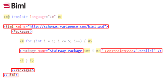
Figure 3 – Highlighted Biml sections within a Biml file
Note: When working on a Biml file in the XML editor in Visual Studio, the XML Schema provides IntelliSense for the Biml elements and attributes that are within the current scope of the XML document.
Biml Script includes the programming language items within a Biml File. Biml Script can be further broken down into Directives and Control Blocks. As a comparison to other technologies you can think of Biml Script as you would ASP or ASP.NET. If you did any ASP development in the past, you will find Biml to be very familiar.
The Biml Script sections are differentiated from Biml sections and are highlighted in red boxes in the following diagram (Figure 4).
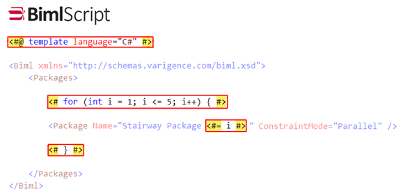
Figure 4 – Highlighted Biml Script sections within a Biml file
We will define all of the key elements of the Biml Language in this article. Additionally we will highlight some of the relevant options from each of these elements. This knowledge will expand your design options in your Biml projects.
Note: The Biml Language is a T4-Like Language (T4 -Text Template Transformation Toolkit) which is based on a template text generation framework.
Text Blocks
Text Blocks are the sections of code that are copied “as-is” to the Biml engine. These sections have not had any preprocessing applied prior to being sent to the Biml engine.
The following example is a Biml text block that gets sent directly to the Biml engine. The Biml engine then complies the XML and produces an Integration Services package named Stairway Package.

Figure 5 – Basic Biml file with one Text Block section
Directives
Directives provide instructions to the Biml engine on how to generate and prepare the Biml file. Directives are typically the first code blocks or code nuggets in a Biml file. The complete list of the supported directives names are the following: annotation, assembly, dependency, import, include, output, property, target and template. For this discussion we will address the assembly, import, include, and template directives.
Directives have the following syntax: an opening “<” followed by the pound sign “#” and the “@” with XML elements and attributes ending with a pound sign “#” followed by a closing “>”
The general syntax of a Directive is shown below.
<#@ DirectiveName [AttributeName="AttributeValue"] … #>
If you have been following the series you have already used the Import Directive in the Stairway to Biml article: Biml as an SSIS Design Patterns Engine – Level 4. If you have not been following the series the below example imports two namespaces into the Biml project with two Import Directives.
<#@ import namespace="System.Data" #>
<#@ import namespace="Varigence.Hadron.CoreLowerer.SchemaManagement" #>
The Import Directive helps with name resolution and will be further discussed in the import directive section.
Assembly Directives
The Assembly Directive allows the use of another assembly’s types or code that is not currently referenced within the Biml Engine. Think of an assembly as a container that contains a grouping of types or code.
This can be thought of as the equivalent process as adding an assembly reference in a Visual Studio project. This enables the use of objects and methods in other .NET assemblies or custom built assemblies.
Assembly Directives have the following syntax:
<#@ assembly name="[assembly strong name|assembly file name]" #>
By default, the following assemblies in Listing 1 are automatically referenced within any Biml project in Visual Studio:
System.dll
System.Core.dll
System.Data.dll
System.Xml.dll
System.Xml.Linq.dll
WindowsBase.dll
BimlEngine.dll*
Listing 1 – Assemblies that are directly available to the Biml Engine
* added via BIDS Helper
Based on Listing 1, most of the common functionality is already available and Assembly Directives are not as common within BIDS Helper Projects. They more commonly used in Mist Projects.
Note: The System.IO namespace that is used for file interaction is located within the WindowsBase.dll and is not needed in an assembly directive because of the assemblies that are referenced by default in a Biml project. Using this namespace with the import directive is all that is need to bring the System.IO namespace into scope. See the import directive section below for more details.
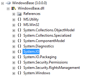
Figure 6 – Some of the namespaces that are included in the WindowsBase.dll file
Import Directives
The Import Directive brings a namespace into the scope of a project and provides access to code without providing a fully-qualified name. You can only import namespaces from assemblies that are currently referenced within the project. This can be thought of as the equivalent process of adding the C# key word: using or the Visual Basic key word: imports in your project.
Import Directives have the following syntax:
<#@ import namespace="namespace" #>
An example of the Import Directive that includes the Varigence.Hadron.CoreLowerer.SchemaManagement namespace is as follows:
<#@ import namespace="Varigence.Hadron.CoreLowerer.SchemaManagement" #>
This enables the Biml Script to call the SchemaManager.CreateConnectionNode() function without using the fully qualified name.
<# var conn = SchemaManager.CreateConnectionNode( "SchemaProvider", "Data Source=.....
Without the import directive, the same call would require the fully qualified name to create a reference to the Varigence.Hadron.CoreLowerer.SchemaManagement.SchemaManager.CreateConnectionNode() function as seen below.
<# var conn = Varigence.Hadron.CoreLowerer.SchemaManagement.SchemaManager.CreateConnectionNode( "SchemaProvider", "Data Source=.....
The Varigence.Hadron.CoreLowerer.SchemaManagement namespace is included within the BimlEngine.dll and is a core namespace used in the interaction with object metadata.
Note: Because WindowsBase.dll is already referenced by the Biml project, to include the System.IO namespace in your project, simply include the following import directive in your Biml file.
<#@ import namespace="System.IO" #>
Include Directives
The Include Directive allows the insertion of text/code from another Biml file into the current file. The included files may also contain other Include Directives.
Include directives have the following syntax:
<#@ include file="filepath" #>
An example of an Include Directive that enables a variable to be referenced from another file is as follows. In this example a file is created i-Parameters.biml (Figure 7) that contains a string variable for the package protection level and is then referenced with an Include Directive to be used within the Main.biml file (Figure 8).
File: i-Parameters.biml

Figure 7 – Contents of the i-Parameters.biml file.
File: Main.biml

Figure 8 –Main Biml file with an Include Directive
The resulting Biml file that will be sent to the Biml Engine is as follows:

Figure 9 – Compiled Contents of the Main Biml file after the Include Directive is applied
Note: the Include Directive takes the text from the i-Parameters.biml file (Figure 8) and substitutes it at the location where the Include Directive was placed. See highlighted code in red (Figure 9).
Template Directives
The Template Directive specifies how the Biml file will be processed. This directive has several attributes that allow configuration of the various aspects of the processing. The attributes that we will cover in this section are the language and the tier attributes.
Template Directives have the following syntax:
<#@ template language="language" tier="tierNumber" #>
The language attribute specifies the language to use within the Control Blocks. The default is set to C# and this option can be omitted if you are coding in C#.
There are two ways to specify the order in which Biml files are compiled. You can use File Selection, within the project, or you can organize the files into tiers, using a Template Directive and the tier attribute.
The tier attribute specifies the explicit order that Biml files are compiled. Tiers are used to make sure that objects are compiled in the specific order that is needed for a multiple file build. This is required when a Biml file needs objects from another Biml file. The referenced file must be compiled first to be able to expose its objects to another file.
Multiple files within the same tier can be compiled in any order, and the developer has no control over the order of compilation within the tier. Hence, files within the same tier cannot reference other objects within the same tier.
As an example: if a file is needed for connection information, then that file must be available prior to the file that uses that connection. More information on tiers is discussed in the RootNode section.
The following example would set the Biml Script language to C# and place the Biml file in the first tier in the compilation order.
<#@ template language="C#" tier="0" #>
Note: Tier is a zero-based attribute.
Without the tier attribute, files are compiled based on the following rules.
- Biml files without Biml Script are implicitly compiled in tier 0 and Biml files with Biml Script are implicitly compiled in tier 1.
- Biml files are then compiled in the order that they are selected.
To use File Selection to dictate compile order, use the following process. In this example we will select the three Biml files to compile them in the subsequent order: BimlScript0, BimlScript1, and BimlScript2.
- Select BimlScript0.biml and hold down the control key
- Select BimlScript1.biml while still holding the control key
- Select BimlScript2.biml while still holding the control key
- Right click the selected files and choose Generate Package.

Figure 10 – Clicking Files in the Correct Order to Direct Compilation
I recommend using the template directive to explicitly set the compilation order of each Biml file and not relying on the implicit rules for compilation or selection order. These methods are prone to errors and should be avoided.
Note: Included files do not need to be selected within the group of Biml files to be compiled.
Control Blocks
Control Blocks are the sections of code that contain C# or Visual Basic and are commonly referred to as Biml Script or Code Nuggets. Control Blocks can use any available .NET API and can reference objects within the selected Biml files through the RootNode object. The RootNode object will be discussed below.
The default language of Control Blocks is C#.
There are three types of Control Blocks that will be discussed below: Standard Control Blocks, Expression Control Blocks and Class Feature Control Blocks.
Standard Control Blocks
Standard Control Blocks are sections of code that help in the generation of text for the Biml output. This capability enables you to turn Biml into a patterns engine that can programmatically create multiple Integration Services packages that have a similar structure.
Standard Control Blocks have the following syntax: an opening “<” followed by the pound sign “#” with C# or VB code ending with a pound sign “#” followed by a closing “>”
<# [C# or Visual Basic Code] #>
The following is an example of the Control Block that was used in the previous article (Stairway to Biml article: Biml as an SSIS Design Patterns Engine – Level 4.) created a C# variable and assigned it to the results of the GenerateTableNodes() function.
<# var tables = connection.GenerateTableNodes(); #>
With the Tables collection above and a Foreach loop we were able to create three packages from the same template using other C# Control Blocks in the Stairway to Biml article: Biml as an SSIS Design Patterns Engine – Level 4.
One of the most common tasks for a standard Control Block is to iterate over a set of objects and replace text in the Biml file with metadata from the looping method. A very basic example of this concept is to create a loop with the For loop statement that will iterate from 1 to 4 and create 4 packages.

Figure 11 – Biml file with Standard Control and Expression Control Blocks
The above code will be processed and the output will be sent to the Biml engine to create 4 separate Integration Services packages. The final output is shown below in Figure 12.
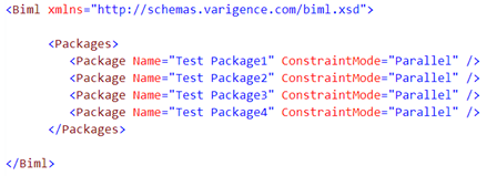
Figure 12 – Final Output from the above Example that is sent to the Biml Engine
Expression Control Blocks
Expression Control Blocks are sections of code that evaluate the expression and then convert it to a string. This string is then inserted into the Biml output. The expression is evaluated first and then converted to a string. Unlike a standard Control Block, Expression Control Blocks can contain programming fragments that are evaluated to a single string.
Expression Control Blocks have the following syntax: an opening “<” followed by the pound sign “#” and a “=” sign with C# or VB code ending with a pound sign “#” followed by a closing “>”
Note: Expression Control Blocks have the basic Control Block syntax with an additional “=” character.
<#= [C# or Visual Basic Code] #>
The following is an example of the Expression Control Block that returns the value 12 to the Biml output. The expression is evaluated prior to string conversion, so explicit string conversion is not required.
<#= 2 + 10 #>
Note: Expression Control Blocks do not end with a semicolon.
Class Feature Control Blocks
The Class Feature Control Block is the only Biml Language feature that has not been used in the previous Biml Stairway series. The Class Feature Control Blocks allow scripted functions that are not included in the initial Biml transform and are used as helper functions to the main Biml transform. These helper functions enable the reuse of common functions within your Biml scripts.
Think of this feature as a way to create methods that can be called from within your Biml Script. With Class Feature Control Blocks you are able to add properties and functions to your Biml Script code that are not part of a complied library. If there are functions that are called multiple times within your Biml Script, they would be good candidates for Class Feature Control Blocks.
Class Feature Control Blocks can be placed in Biml files that include other Biml or Biml Script but must be placed at the end of the file. I recommend making a separate file for your Class Feature Control Blocks and calling them with the Include Directive. If the Include Directive is used to include the Class Feature Control Blocks within the file, the Control Block does not need to be placed at the end of the file.
Class Feature Control Blocks have the following syntax: an opening “<” followed by the pound sign “#” and a “+” sign with C# or VB code ending with a pound sign “#” followed by a closing “>”.
Note: Class Feature Control Blocks have the basic Control Block syntax with an additional “+” character.
<#+ [C# or Visual Basic Code] #>
A very contrived example might be to include a function that creates an upper case string. This function could easily be achieved by using the ToUpper() function within your C# Biml Script and is only being used to demonstrate the use of a Class Feature Control Block.
In this section, we will demonstrate two methods of using the Class Feature Control Blocks, a single file example and a multiple file example. The example below uses a Class Feature Control Block to set the package name to an upper case string, calling the UpperCase() function from within the same file.
A single file solution (Figure 13)
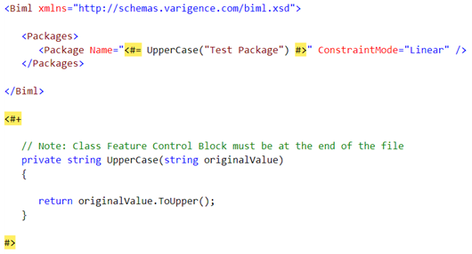
Figure 13 – Single File Class Feature Control Block Example
In this example we will use one file that contains the Class Feature Control Block and one file that includes a reference to the Class Feature Control Block using an Include Directive. This is the recommended method of using a Class Feature Control Block which enables code reuse.
A multi file solution (Figures 14 and 15)
File: i-Functions.biml
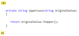
Figure 14 – i-Functions File for Multi-File Class Feature Control Block Example
File: Main Biml:

Figure 15 – Main Biml File for Multi-File Class Feature Control Block Example
RootNode
The RootNode is an in-memory representation of the objects from the selected Biml Files. It is the top level entry point back into the project objects and is built based upon tiers. Tiers define which objects are available to the subsequent tier in compilation. This order is dictated by the default rules in combination with file selection (stated above in the Template Directives section), or the template directive tier attribute. The RootNode only includes files in the project that were selected in conjunction with the Generate SSIS Packages menu option.
To make the above definition easier to understand, let’s look at an example with diagrams. The example includes two files: 1.1-Environment.biml and 2.x-Package Group A.biml.

Listing 16 – 1.1-Environment.biml file
The 1.1-Environment.biml file has the tier attribute value set to 0 (first red box) and has two connections. We will reference the Source connection (second red box) from the 2.x-Package Group A.biml. The blue boxes in both diagrams represent incomplete data that was removed and not relevant for this discussion.
The 2.x-Package Group A.biml file (see Listing 17) has the tier attribute value set to 1 (first red box) and will compile after the 1.1-Environment.biml file based on tier levels. This is required because we will need to reference the connection to get the required data elements from that object prior to the compilation of the 2.x-Package Group A.biml. We will reference the Source connection by using the Control Block code: RootNode.OleDBConnections[“Source”] (second red box). From the RootNode object we have access to everything that was compiled in the tiers prior to the current tier of the file being compiled.
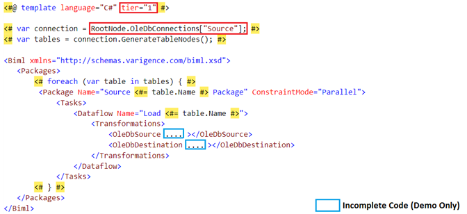
Listing 17 – 2.x-Package Group A.biml file
To generate the Integration Services packages, we will select the two files, right click and select the Generate SSIS Packages menu option, as shown in the diagram below.

Figure 18 – Multi-Selecting Files that will be Included in the RootNode
Note: Based on the above diagram the objects from the x.2-Package Group B.biml file will not be included in the RootNode object during this compilation, because it is not selected.
Now we will step back and look at the building of the RootNode object through all of the tiers in the above example.
During the compilation of Tier 0, the RootNode does not contain any objects from the selected Biml files. If the 2.x-Package Group A.biml file was compiled in Tier 0, the OleDBConnections would not exist and would cause compilation errors.

Figure 19 – 1.1-Environment.biml file and the RootNode object prior to start of Tier 0
During the compilation of Tier 1, the RootNode will contain all of the objects from the Biml files that were compiled in the tier before it (Tier 0). This includes all of the objects that were compiled in Tier 0. At this point in the compilation of 2.x-Package Group A.biml, the OleDBConnections objects do exist and are accessed through the RootNode object.
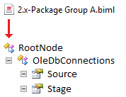
Figure 20 – 2.x-Package Group A.biml file and the RootNode object prior to start of Tier 1
For discussion purposes, if there was another tier (Tier 2) in the compilation process the below diagram would be the representation of the RootNode that would be available to Tier 2.
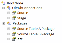
Figure 21 – the RootNode object prior to start of Tier 2
The RootNode object is quite large and would require another article to define its contents. I would suggest taking a look at the Varigence online documentation for a complete list of objects within the RootNode (https://www.varigence.com/Documentation/Api/Type/AstRootNode). The most commonly used objects within the RootNode are collections like: Connections, FileFormats, Packages, Tables and Schemas.
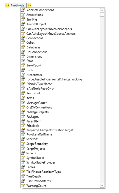
Figure 22 – Listing of all of the Properties within the RootNode Object
Note: Analysis Services objects are included within this list but are only available for use within the Mist product.
Conclusion
In this article we have taken a tour of the objects that are available within a Biml project using the BIDS Helper add-in. Gaining an understanding of the above objects, we are able to create more modular projects and work toward better project design and code reuse. This article provided the building blocks to create a more enterprise level Biml solution.
The next article will discuss best practices by applying what we have learned in this article to create a more robust solution.
